Thermatron Michigan Mitty Might QRP Transmitter Kit

Everything you need to “homebrew build” this cool Thermatron QRP CW 40M Transmitter.
This new kit from Hollow-State Designs is a thermatron version of the original transistor Michigan Mighty Mite (MMM), a simple CW QRP 80M (or 40M) crystal controlled transmitter. The original version was intended to be very simple and very inexpensive utilizing a low cost TV color-burst crystal at 3.579 MHz. This version uses a 6C4 thermatron and is designed to transmit on the CW portion of the 40M band. I call it the TMMM.
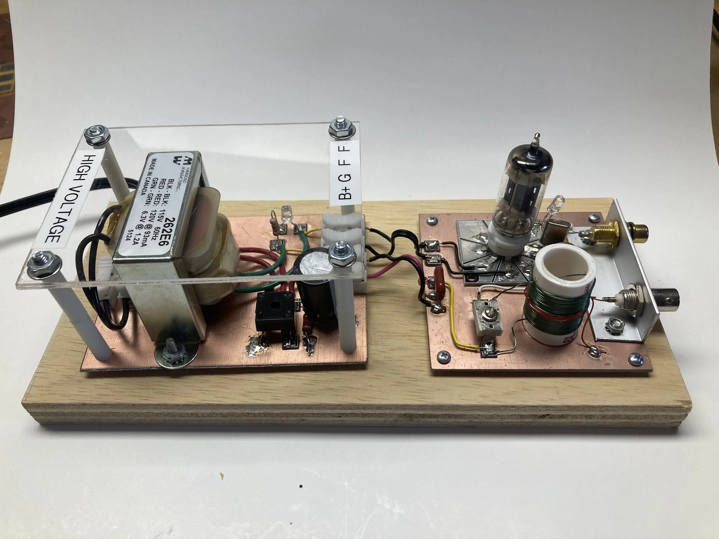
The photo shows the assembled kit mounted on plywood with an optional HV power supply (see below). More details and history of the MMM can be found on Bill Meara's soldersmoke blog.
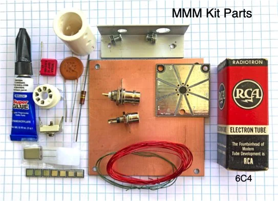
Everything you need is in the kit including detailed assembly instructions (download PDF here). Everything is soldered directly to the board or to a component pad that has been super glued to the board. There is no through-hole soldering,
A link to a full length video of the design and construction of an early version of the TMMM is included in the assembly instructions (also on the Video page). The video takes you through how to design and build the circuit from scratch. The kit is an improved version of the hollow-state MMM in the video and is based on my world famous book, Hollow-State Design.
Specs
Required power: 6.3V AC or DC at 150 mA, Up to 300V (typically 150-250V) DC at 25 mA
Thermatron: 6C4 (tested)
Output power: about 350 - 400 mW into a 50 ohm load. It depends on the plate voltage you supply the 6C4. Max plate voltage is 300V.
Transmit Frequency: the kit is supplied with a crystal in the CW portion of 40M (7030, 7040, 7055)
Second harmonic level: about -39 dB from carrier level. Due to the very low harmonic output power (< 1uM) no LPF is supplied.
Powering
The TMMM needs 6.3 V (AC or DC) at 150 mA for the filament and anywhere from 150 to 250 Volts for the B+ (6C4 plate circuit). You can power the transmitter from the HSD High-Voltage Power Supply kit (see description below). It outputs 190V DC and 6.3V AC and easily attached to the TMMM.
HSD’s HV Power Supply Kit
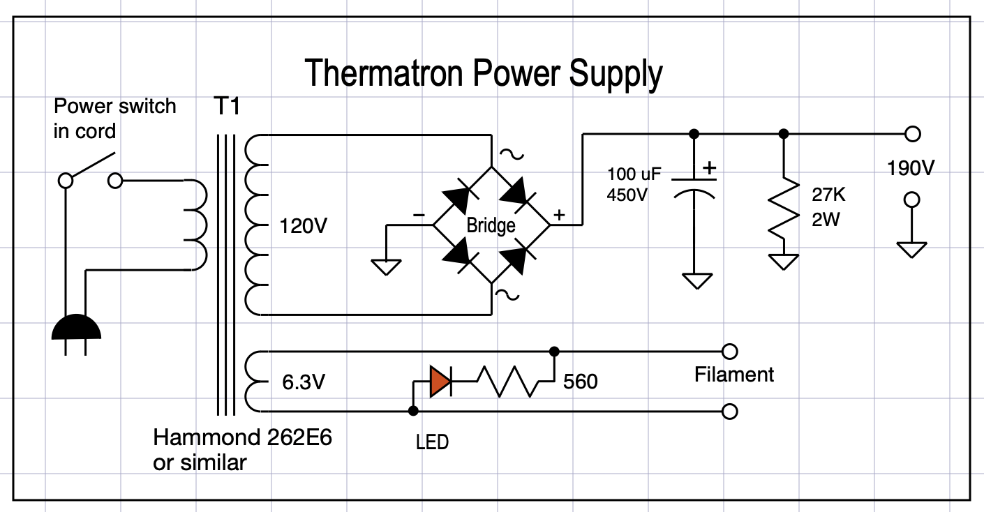
The HSD Thermatron Power Supply kit is a simple high-voltage supply intended to provide power for the TMMM QRP CW transmitter as well other thermatron projects and future HSD kits. The supply outputs around 190V DC at 90 mA, and 6.3V AC at 2 A. These voltages are dependent on the line voltage in your area and are based on a 115V line voltage—low in most areas in the U.S.
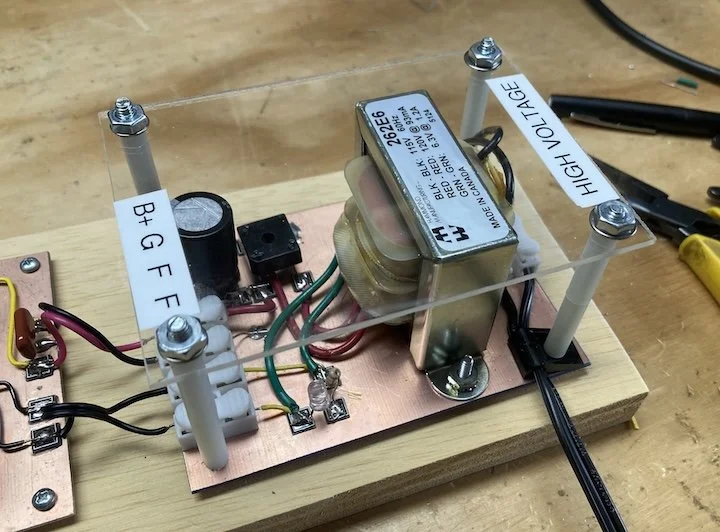
The transformer HV is bridge rectified and filtered to produce the 190V DC. The transformer rating of 90 mA is plenty for thermatron work. A 27K bleeder resistor helps stabilize the supply and bleeds off HV when you turn it off. An LED is attached across the filament supply to indicate the supply is on.
The photo left/below is the supply when completed. It is built on a 3 1/4 by 4 1/2 inch copper-clad board. Construction is similar to the TMMM, Everything is soldered or glued to the board. There are only 6 components and the layout is not critical. There is a plexiglass cover to help prevent you accidentally touching anything when the power is on. It uses insulated spring loaded connectors to connect to the power line and the TMMM or other project.
Like the TMMM, everything you need is in the kit including all hardware and labels. All parts are super-glued to a copper clad board. There is no through-hole soldering, everything is soldered directly to the board or to a component pad that has been glued to the board.
Complete step-by-step assembly instructions are available on my YouTube Channel.
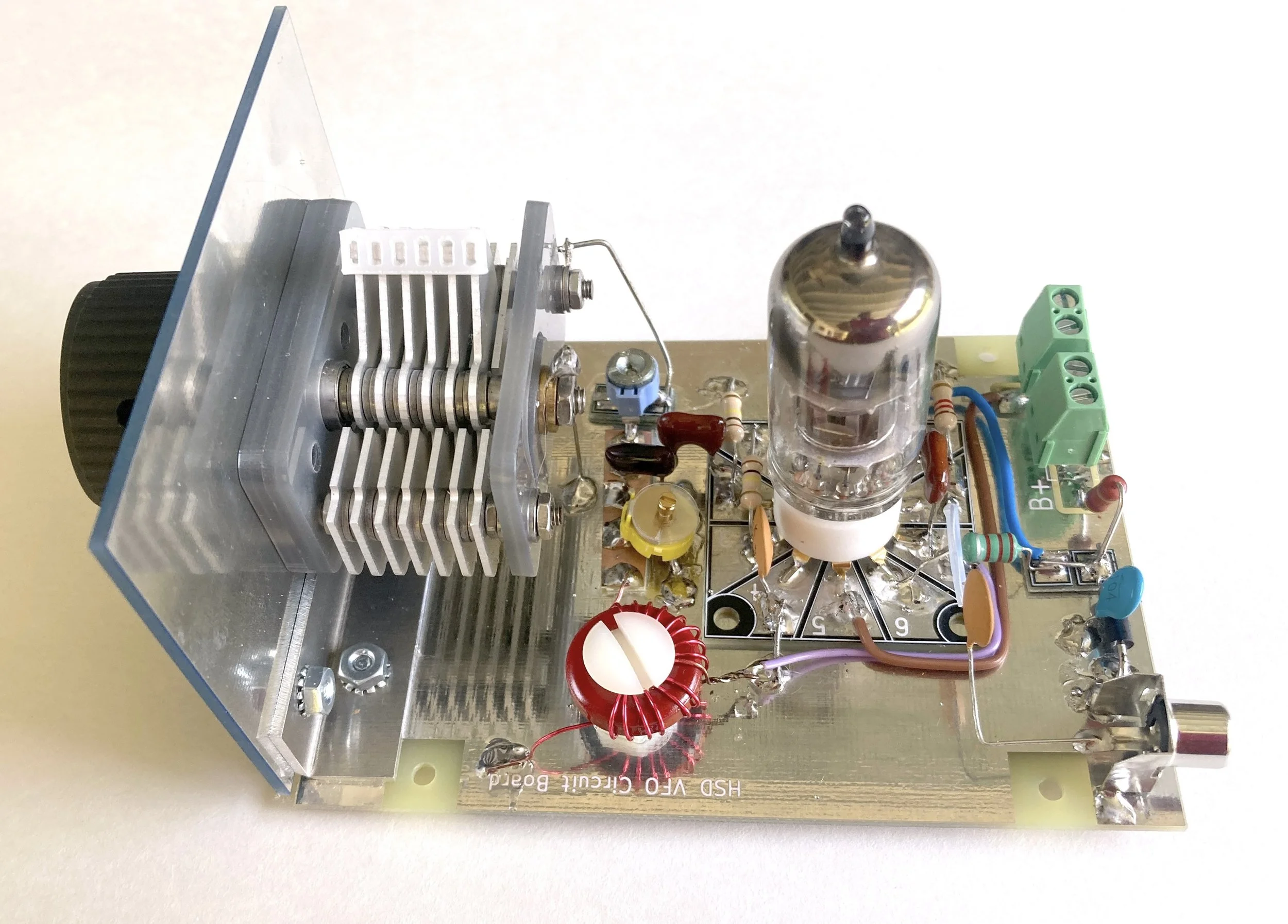
HSD Thermatron 40M VFO Kit
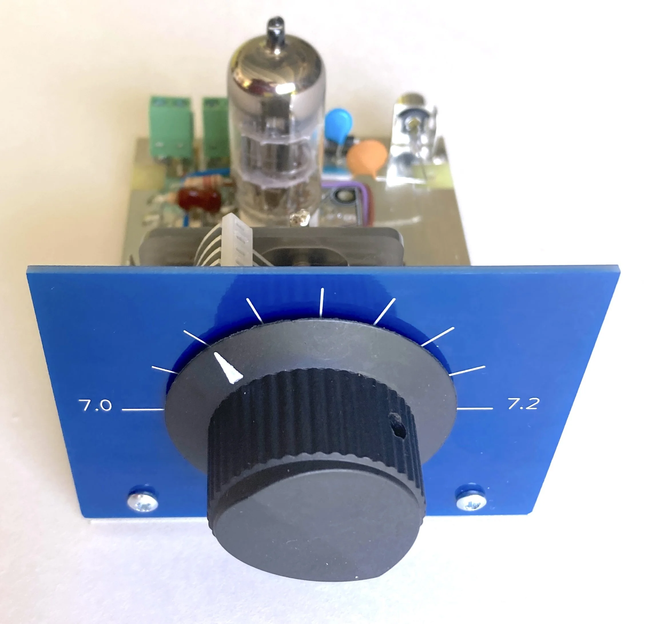
Everything you need to “homebrew build” a complete 40M (7.0 - 7.2 MHz) VFO (Variable Frequency Oscillator)
This new kit from Hollow-State Designs is a complete “homebrew” thermatron VFO that covers the 40 meter amateur band from 7.00 go 7.20+ (the CW portion and much of the SSB/AM portion). In the spirit of our Thermatron Michigan Mighty Mite (MMM), this is a simple to build project with everything provided including all hardware, parts, even the superglue.
This VFO/LO is the first of our 3 kit DCR (direct conversion receiver), providing the receiver band tuning. The kit can also be used to supply a 4 Vp-p stable signal to a homebrew transmitter (such as the TMMM) or as a LO in your next receiver project. It uses a common 6U8A pentode/triode. The pentode is the Hartley oscillator with a triode cathode follower. Like our TMMM, this kit was created to familiarize new and existing hams with simple thermatron (vacuum-tube) homebrew construction techniques.
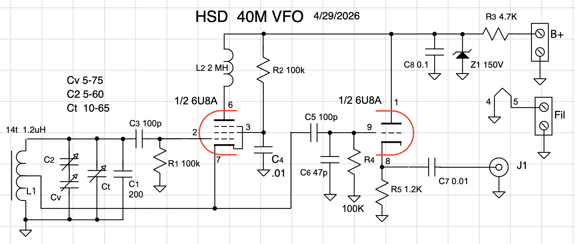
The VFO needs a minimum of 160V DC at 25mA, and 6.3V AC for filaments. The kit was designed to use our HV PS which outputs 190V DC and 6.3V AC
Complete step-by-step assembly instructions are available on my YouTube Channel.